A First Example
Activating the Logic Nodes Add-on
The Logic Nodes add-on comes pre-installed in UPB eGE 0.3+. If not already, it needs to be activated:
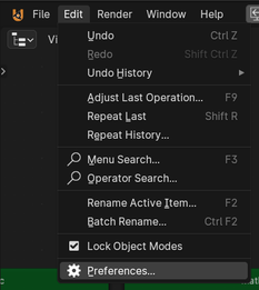
Navigate to Preferences
There, search/filter for logic, and check the box for Logic Nodes+.
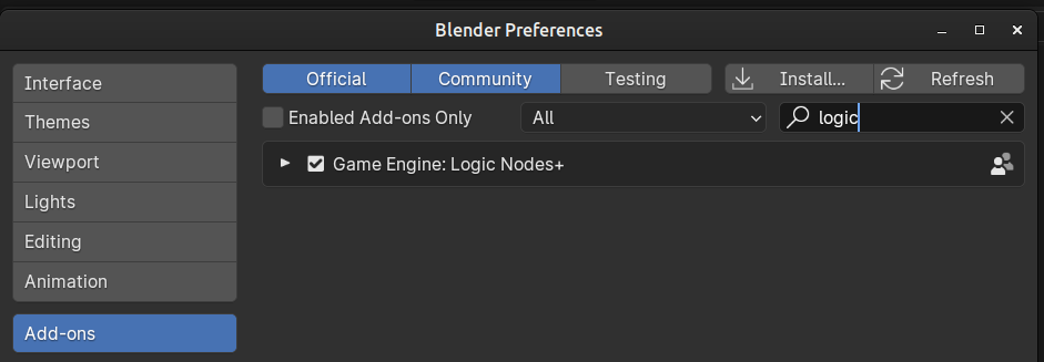
Search for ‘logic’ and check the box
Click the little arrow, next to the check box, to expand the Logic Nodes+ add-on menu, and in the click button.
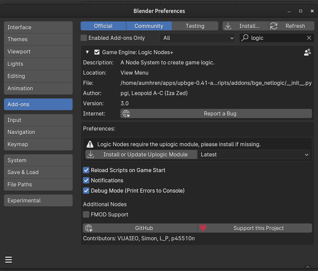
Install or Update Uplogic Module
Important
This same menu can be used to report a bug > click button (internet connection is required). The default web browser will open github.com web page. There, click button, and follow the instructions.
Houston, the eagle has landed. We’re good to go.
System Console
UPBGE uses system console/terminal to print info and error messages. To see those messages:
Windows users:
menu.
Linux and Mac users:
- start UPBGE via console/terminal - navigate to blender executable file, and run::
./blender
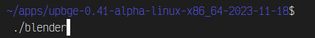
Run UPBGE on Linux or Mac terminal
We will print some text to the console when a keyboard key is pressed. This is the “Hello World” example for the Logic Nodes.
Creating a New Logic Tree
Now let’s get started. First we need to create a logic tree. Switch the Editor Type to the .
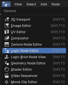
Select Logic Node Editor
This editor is similar to the Shader Editor or Geometry Node Editor. Click on and a new empty tree (named Logic Node Editor by default) will be created.
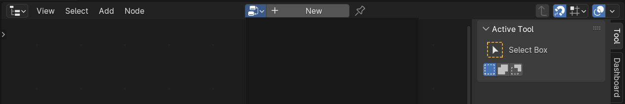
Click New button
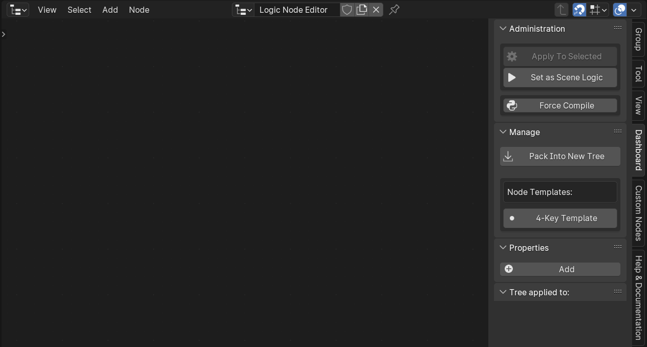
New empty Node Tree with side Dashboard
Adding Nodes
With mouse cursor inside Logic Node Editor, press Shift-A, or click button in top header. This will pop-up a menu with all available Logic Nodes, organized in sub-menus. Go ahead and take a look at what is available.
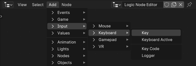
Available Logic Nodes in Add menu
For this example, we’re looking for two nodes: Keyboard Key and Print node. Easiest way to add nodes:
press Shift-A hotkey, to invoke adding a node;
immediately after that start typing, i.e.
print- UPBGE is smart and will search for it;if accidentally wrong node is selected, press ESC to cancel, and repeat.
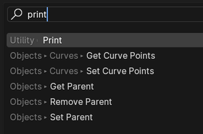
Editor searches for node
Tip
Beside finding the node, Search pop-up also shows in which menu/sub-menu the nodes are.
Keyboard Key node is a node of the condition type. These nodes do not actually do anything in-game; they either provide a condition, or can be used to check for a more complex set of conditions.
Print node is an action type node. These nodes actually do something. They move objects, change properties, add constraints etc. - you name it.
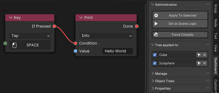
Those two nodes need to be connected together. The Keyboard Key node has an If Pressed output socket, colored red. Connect it (click-and-drag) to the Condition input socket of the Print node and enter “Hello World” in the text box at the bottom, next to Value input socket (blue sockets are for strings). Also, if not already, look at the Keyboard Key node and you’ll see that it expects user to choose a key. Click the bottom field and press SPACE key, which will set that key as selected one. It should look something like this now:
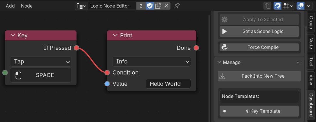
Logic Nodes added and connected
Applying Logic Trees
Once done, all that’s left is to apply the tree to an object. Logic trees work the following way:
each tree can be applied to as many objects as you want;
meaning it is executed by each object it is applied to, separately.
Example: if this tree is attached to 4 objects and user presses SPACE key once, the message would be printed 4 times, once for each object.
To apply a tree to a cube, first a cube is added; select it and press button, in the Dashboard tab of side N-panel. Press N to toggle N-panel, if it is hidden.
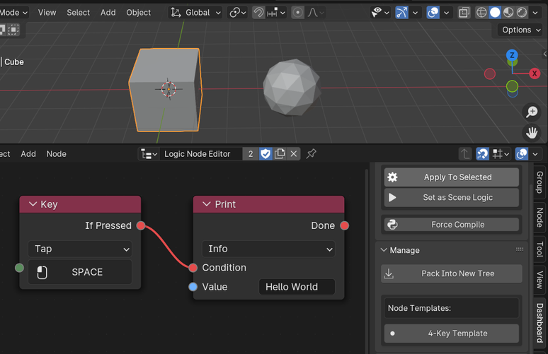
Apply logic tree to selected object
Warning
Be careful, trees can be applied to multiple objects at once!
To see which objects have been applied with a Logic Node tree, scroll down the Dashboard tab, and check the Tree applied to: sub-panel at the bottom.
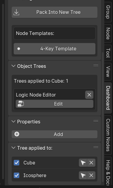
Objects with applied Logic Node tree
If needed, sub-panels can be rearranged:
for easier rearranging, first collapse sub-panels - click small arrow next to the sub-panel title;
click-and-drag top-right icon (4 by 2 dots) of sub-panel.
Collapsed and rearranged N-panel sub-panels
What is left now is to run our example 'game':
in Render panel of a Properties editor, click or (hotkey is P) - the 'game' shall start;
with 'game' running, press SPACE (or whichever keyboard key is assigned in Keyboard Key node) once;
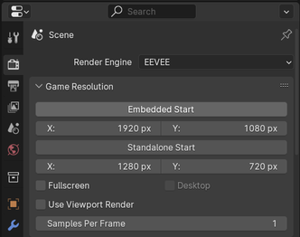
Start the game in Render panel
Finally check the system console - it should have our message printed:
once if logic tree was applied to one object;
twice if logic tree was applied to two objects;
four times if logic tree was applied to two objects, and SPACE was pressed twice etc.
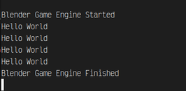
System console/terminal output
Note
See System Console for more info.
The Print node prints to the system console only, not to the Python interactive console. This is a feature of Blender and is not changeable.
Press ESC key to end the 'game'.