Blender/UPBGE Basics
Blender/UPBGE
When you start Blender/UPBGE, you will be greeted with the splash screen. Although you can customize all aspect of Blender/UPBGE, in this manual we will assume you are using the default Blender/UPBGE settings and shortcuts.
Clicking anywhere else to dismiss the splash screen, you are presented with a default workspace.
Blender/UPBGE workspace
Blender/UPBGE window is divided into Editors. Each Editor region can be resized, moved, and changed to display a specific set of content. For now, let’s focus on the default setup.
Main Menu
At the top of the screen is the main menu, which offers basic functionalities such as File, Edit, Render and Help.
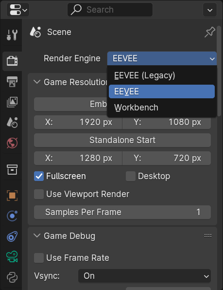
Selecting the Game Engine
By default, EEVEE render engine is selected. This engine enables certain features that are not accessible normally, and also disables features that are not available in UPBGE.
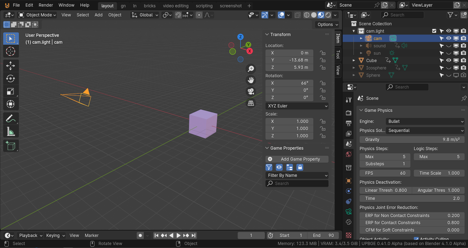
3D Viewport
Occupying the majority of the screen is a 3D Viewport. Here you can see the 3D world you created and test the game. For now, feel free to explore the 3D Viewport by holding down your middle mouse button over the 3D Viewport and dragging the mouse; the view should rotate with the mouse movement. (Mac users can use the two-finger rotate gesture on the trackpad.) The default scene contains three objects: an immortal Cube, a camera, and a light. To select one of the objects, click on it.
Note
Basic Navigation Controls
There are more than one way to navigate in UPBGE. Hold MMB to rotate the 3D view, scroll the Wheel to zoom in/out the 3D view. LMB to select a 3D object. Selected objects are highlighted in yellow. RMB to open context menu. Another way is Ctrl-MMB > move mouse to zoom, Shift-MMB > move mouse to pan. Not much new here, those are standard application navigation actions.
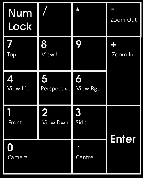
Numpad with default assigned views
Another common setup for the 3D Viewport is to split the view into four quadrants: top (Numpad 7), front (Numpad 1), side (Numpad 3) and a perspective/orthographic (Numpad 5) view. Turn on Quad view by Ctrl-Alt-Q with the mouse over the 3D Viewport. Press the same key combination to go back to the single view.
To quickly snap to one of the predetermined views (side, top, front, and so on), the number pad is the way to go.
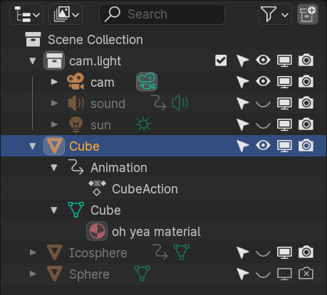
Outliner Editor
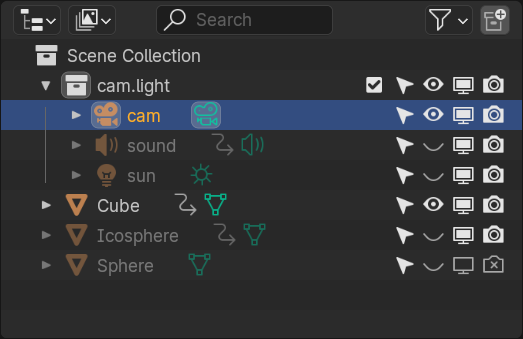
Outliner editor
To the right of the screen are two editors. The top portion is the Outliner, which contains a listing of all the data in the current Blender file. For a large project, the Outliner is an indispensable tool for organizing your scene. For now, you can safely ignore it.
Properties Editor
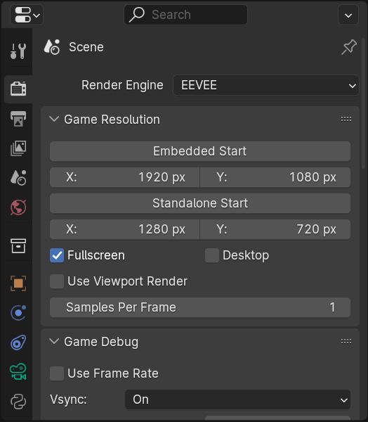
Properties editor
Under the Outliner on the right, you have the Properties. Here you can access global settings for the file, as well as settings for individual objects. This is one of the most frequently used panels in Blender, after the 3D view perhaps. The Properties Editor is context sensitive, which means it will automatically display different content, depending on the object that is active. Take a closer look at the icons on the left side of the Properties, as shown in figure. These tabs organize the properties into groups, with the more general settings on top, and more specific settings at the bottom. Mouse-over the tab, the popup will tell the name of it ( to enable the popup).
Timeline Editor
At the very bottom of the screen is a Timeline window, which will be useful when you start making animations.

Timeline
Workspace Customization
The default screen, as described previously, is set up for general use. At some point, it becomes necessary to change the screen layout to accomplish other tasks. To select a different workspace, click the workspace tabs at the top.
Apart from the predefined workspaces, you can customize each one however you like. You can either split an existing editor into two or merge two adjacent editors together.
Note
Editor, Region, and Area
A region within the Blender/UPBGE window is called an editor. An editor displays a specific set of content and tools. Common areas include: 3D Viewport, Properties, UV/Image Editor and more. Specific to UPBGE are Logic Brick Editor, Logic Brick Node View and Logic Node Editor.
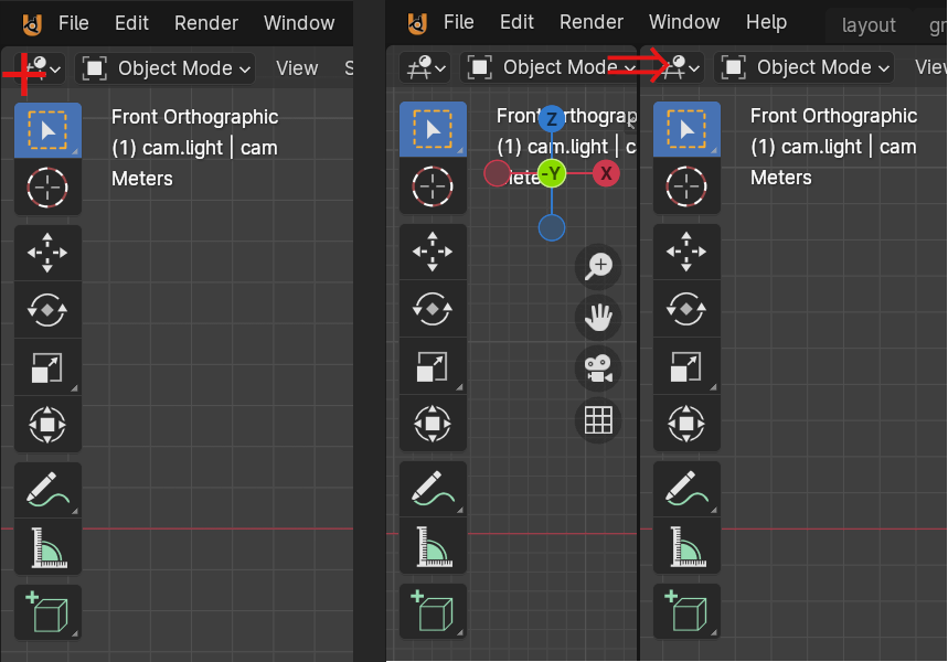
Area/window splitting
Figure shows one area split into two. You can do it by dragging the top corner of the area to the right or bottom.
To merge two adjacent areas into one is exactly the same as shown in figure, but it is done in reverse order. Optionally, RMB on the edge between area(s) you want to split or join, and select the option in the pop-up menu.
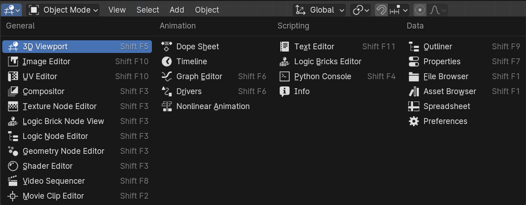
Editor selection
Not only can you change the size and layout of the editor, but the type of editor can also be changed. As you can see in above figure, the left-most icon in the header can be used to change the editor type.
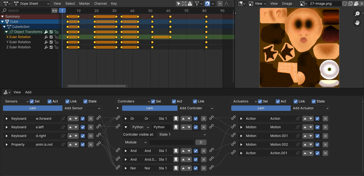
Dopesheet, Image Editor, and Logic Brick Editor
Almost everything a studio needs to create the game is integrated into a single interface: you can create the game, test the game, and play the game all from the same app. This means that, as an artist, you can create a game in the shortest time possible, without having to worry about importing and exporting files between different applications. As a programmer, you won’t have to switch back and forth between different software just to test your code. Figure above shows some screenshots of different editors that you will be using throughout the manual.
More on the 3D View
3D view is where you will spend most of your time, so let’s take a look at it in a bit more detail. You’ve already learned a few ways to navigate around the scene earlier in this chapter, using both mouse and the keyboard.
Viewport Shading Modes
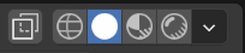
Viewport Shading Modes
Four different Viewport Shading modes available are used to change the way the scene is displayed onscreen. Those are:
Toggle X-Ray - enables X-ray of all objects; useful when the scene gets really complex; not a Viewport mode per se, rather an option.
Wireframe - draws all objects as wireframe, which allows you to see through objects.
Solid - draws all objects as solid faces, which is commonly used when modeling.
Material Preview - draws all objects as solid faces, with texture and accurate lighting. This is useful for previewing the scene.
Rendered - draws all objects as they will be rendered, also with texture and accurate lighting. This is how final rendered scene will look like.
Two most commonly used Shading modes are Solid and Material Preview. Press the Z > number/hotkey (underlined) to pop-up a circular selector and select desired mode. Alt-Z to toggle X-ray on and off - only available in Wireframe and Solid Shading mode.
Note
Standing Out
Individual objects can override the Viewport Shading mode via .
Editing Modes
Far to the left of the Shading mode selector is the Editing Mode selector.
Object Mode - the default mode, which allows the manipulation of objects in the scene as a whole. From this mode, you can select any object in the scene, then move, rotate and scale it. In fact, almost everything apart from modeling can be done from Object mode.
Edit Mode - this mode can be seen as the counterpart to Object mode. It allows you to edit the underlying geometry of the object. If you are modeling, you’ll probably want to be in Edit mode, except if you are sculpting. For this reason, Edit mode is not available when a non-editable object is selected (for example, a camera or light).
To switch between Object mode and Edit mode, press the Tab key.
In addition to the two editing modes we just discussed, there are a few other modes that are less commonly used.
Sculpt Mode - only available for Mesh objects. Allows modeling the mesh as if it were clay.
Vertex, Weight and Texture Paint Mode - only available for Mesh objects. These modes allow the assignment of color or weight to the mesh.
Pose Mode - is used to animate bones in an armature. Only visible when Object has bones attached.
Edit and Object mode are by far the most commonly used editing modes, so we will refrain from diving too deeply into the other modes for now.
Keyboard and Mouse
The joke is that to move an object in Blender, you have to press the G key, which stands for movinG. This gag stems from the fact that to a beginner, many of the shortcuts in Blender/UPBGE seem counter-intuitive. However, there is a very good reason why G is preferred over M - it can be easily accessed on the keyboard by the left hand while the right hand is on the mouse. Also, officially, G stands for Grab.
Note
Think Different
By default, Mac keyboard uses Command instead of Control as the default modifier key. So whenever you see Ctrl-Something, mentally map it to Cmd if you are using a Jobsian product.
Additionally, Blender/UPBGE has good support for multi-touch gestures on OS X. You can pinch to zoom, rotate to orbit around, and pan around.
Shortcuts that work the way you would expect:
Ctrl-S - save file;
Ctrl-O - open file;
Ctrl-N - new file;
Ctrl-Z - undo;
Ctrl-Shift-Z - redo;
Ctrl-Q - close (quit) application.
Those shortcuts work anywhere within Blender: they are effectively global. Unfortunately, the familiarity ends here.
To manipulate an object in the 3D view, generally you have to select it first:
LMB - select object;
Shift-LMB - extend selection to multiple objects;
A` - select all;
Shift-A - deselect all.
All actions above are “reversible”. If something is already selected, LMB on it will deselect it. If all the objects are already selected, double-tapping A will deselect all.
Once an object is selected, you can manipulate it. The keyboard shortcuts below correspond to the three most basic transforms:
G - start grabbing;
S - start scaling;
R - start rotating;
Move mouse - carry out transform action;
LMB - confirm transformation;
Enter - confirm transformation.
Pressing one of the keys will start the transformation, and then you can move a mouse to transform/move the object. To finalize the transformation, LMB or Enter.
Search
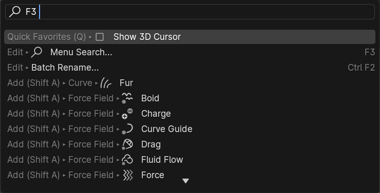
F3 Search Box
The final tip that you will learn is the search functionality. If you are unable to recall how to invoke a certain operation, whether through a button or a keyboard shortcut, a quick way to find it is by using the search functionality. Press F3 key and start typing in what you are looking for, and the result should appear.
Blender/UPBGE Philosophy
Blender/UPBGE is designed with certain philosophies in mind. Understanding these will allow you to use Blender the way it is intended, which allows you to navigate around Blender faster and work more efficiently.
Let the brainwashing begin!
Interface
Because Blender was originally created as an in-house software, its interface is designed to maximize speed and efficiency for users who have mastered it. Since Blender 2.5, a lot of work has been done to make the interface more user-friendly. That said, Blender is probably unlike any other program you’ve used before, including other kinds of 3D software. Luckily, the Blender interface is very consistent within the application. This means that once you learn to do something, you’ll be able to use it in another part of the program.
Keyboard
Because of the large number of commands Blender is capable of performing, invoking a function through a quick tap on the keyboard is generally faster than using the mouse to find the menu entry. As you follow through the rest of this section, pay special attention to the shortcut keys that are used, because Blender is designed to let you work fast once you learn the shortcuts.
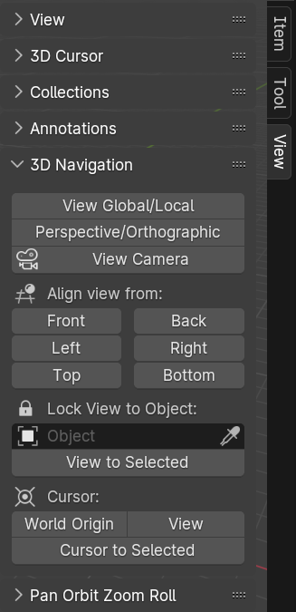
N-panel > View > 3D Navigation
Blender’s keyboard shortcuts are optimized for a full-sized English QWERTY keyboard. The number pad (which, unfortunately, is not present on many laptops) is used to quickly navigate around the 3D scene. Laptop users usually have to press extra keys on their keyboard (such as the Fn or a toggle) in order to simulate a number pad key. As a solution, go to tab and enable option to use main 1 to 0 keys instead of Numpad keys.
Alternatively, Blender also has an add-on called 3D Navigation that provides an easier way to navigate around the world for people without a number pad. To enable the 3D navigation plug-in, enable add-on. Then you can switch views quickly from the 3D view’s Toolshelf.
Mouse
Blender is designed for a three-button mouse: a mouse with two buttons and a scroll wheel. Although there is an option to emulate the middle-mouse button (when you click on the scroll wheel), this book will assume that you are working with a three-button mouse for convenience.
Note
How to Emulate a Three-Button Mouse
If you don’t have a three-button mouse, you can use the Alt-LMB combination to emulate the middle mouse button. To enable this feature, go to and turn on . On some Linux distros, it is possible to press LMB & RMB at the same time to emulate MMB press.
Context
In Blender, the actions you can perform at any given time are limited to the current state of Blender, also known collectively as the “context”. For example, certain operations can only be invoked when you have an object selected; the Property Editors change, depending on which object is selected; the effect of the keyboard shortcuts even changes, depending on where your mouse is positioned. This context-sensitive nature lets you focus on the task at hand by only providing you with options that makes sense at the time. This is Blender’s way of preventing the interface from getting too cluttered.
The “context” usually refers to one or a combination of the following:
Active rendering engine - EEVEE and Workbench are available.
Active editor - is defined as the window subdivision that the mouse cursor is hovering over. Shortcut keys often have different effects, depending on which editor the mouse is over.
Active object - is defined as the object that is most recently selected.
Selected object - all the objects that have been selected (highlighted). Keep in mind that there can be more than one selected object, but only one active object.
Editing mode - Blender has six different modes of editing; most commonly used are the Edit mode and the Object mode. In Object mode, you can manipulate objects as a whole. In Edit mode, you can change the shape of a mesh. In each mode, there is a unique set of tools and options at your disposal. You will learn about the other four modes (Sculpt, Vertex Paint, Texture Paint, Weight Paint) in later chapters.
Datablocks
Often, a single Blender file contains hundreds of objects, each with different colors, textures, and animations. How is all this organized?
Blender uses “data blocks” to represent content stored within a Blender file. Each data block represents a collection of data or settings. Some common datablock types you will encounter are Object, Mesh, Material, Texture and Image datablock.
Datablock hierarchy
In order to reduce the apparent complexity of the program, Blender further organizes data blocks into hierarchies. At the top level are scenes, which can have a number of worlds, each of which can have any number of objects (objects can be a mesh, a light, a camera, and so on). If the object is a mesh, then a Mesh datablock is attached to it. If the object is a light, then a Light datablock is attached to the object.
Throughout the Blender interface, you will run into many datablock managers. They all look like the figure aside.
Because datablocks can be shared, copied, and reused, large scenes can be managed efficiently through the use of shared datablocks.
Parenting and Collections
Collections and parenting both allow you to introduce some form of order to the scene by setting up arbitrary relationships between different objects. But collections and parenting work in different ways.
Parenting is used to establish links between multiple objects so that basic transformations like location, rotation, and scaling are propagated from the parent to its children. This way, any transformation applied to the parent is automatically applied to all the children. Parenting is a useful way to “glue” different objects together so they behave as one.
To parent one object to another, simply select the object you want to be the child first. If more than one object is to be a child, select all of them. Select the object that you want to be the parent last. Ctrl-P to parent them.
An object can only have one parent object, but a parent object can have many children. Manage parent/child relations from .
Collections can also be used to logically link objects in the scene together without any transformation constraints to the objects. Unlike parenting, collection does not have a parent-child relationship; objects are simply members of a collection.
Select all the objects you want to group, Ctrl-G to add them to a new collection. You can also manage collection membership from .
Collection, by itself, it not very useful. But collection can be quickly “instanced”. Collection Instance is a very useful way to create multiple copies of objects without making actual copies of the objects. Collection will also come in handy for asset management, which will be discussed in another chapter.
A single object can be in multiple collections. A collection can have multiple objects.
Backward Compatibility
Blender is designed so that older files can be opened with newer versions of Blender. But due to the rate that Blender matures, some unexpected behaviors are to be expected when you least expect them.
Due to the Blender Python API change in Blender 2.5, old scripts written for 2.4x will be broken in later versions of Blender. But by the time you are reading this, there should be enough new content available for you to find.
Onward
This concludes the crash course on Blender and the game engine. By now, you should have a cursory understanding of the function of a game engine and be familiar with the Blender interface. In the next chapter, you will get your hands dirty and build a simple game by following the step-by-step tutorial.